ASAP NextGen
“ASAP NextGen is a new paradigm in optical simulation software for predicting real-world performance.”
Design and Analyze Imaging and Illumination Systems with CAD Interoperability
Design and Analyze Imaging and Illumination Systems with CAD Interoperability
ASAP® NextGen is powered by the ASAP non-sequential raytracing engine – known throughout the optics industry for its accuracy and efficiency. Rays can encounter surfaces in any order and any number of times, with automatic ray splitting and/or scattering. Optimized for speed with new CoreMax parallel processing technology, ASAP will trace millions of rays in minutes.
Use ASAP NextGen to model complex imaging systems, illumination systems, and light concentrating devices. Create highly accurate source models using source images, point sources, ray grids, and ray fans. Model LED’s, incandescent bulbs, HID arc lamps or CCFL’s or import from the BRO Light Sources Catalog. Perform the analyses necessary to validate your designs without experimental prototyping.
Customers in need of CAD software solutions may also purchase a license of SOLIDWORKS® 3D CAD software to complement their ASAP optical software solution. Multiple configurations of SOLIDWORKS Parts, Assemblies, and Drawings are available. SOLIDWORKS is an intuitive 3D-design environment optimized for use with ASAP. Write ASAP geometry files from within SOLIDWORKS, import XML files, or use BRO’s proprietary smartIGES™ CAD translator to import system models from SOLIDWORKS and other CAD packages while maintaining fast, efficient ray-tracing speed.
In addition to parallel processing with CoreMax technology, ASAP NextGen includes Remote distributed processing capability allowing you to complete big design jobs in a fraction of the time required by other tools – spawn up to (5) additional ASAP NextGen sessions on your Local Area Network (LAN), without leaving your desk.


Request a Free Trial
Breault Research Organization is pleased to provide full versions of ASAP, APEX and RefCAD for your evaluation.
Fill out and submit the form to get started.
If no response within 48-hours, check your spam folder.
ASAP NextGen is a Redefining Moment in the History of ASAP and the Future of Design
ASAP NextGen, a product of more than 30 years of continuous development, is not only the next step in the evolution of the ASAP program, but a complete re-imagining of the ASAP environment. ASAP NextGen offers engineers and product designers a host of new features making it the easiest to use ASAP ever and greatly improving on the unmatched capability, flexibility, speed and accuracy for which ASAP has long been known. ASAP NextGen is a new paradigm in optical simulation software for predicting the real-world performance of automotive lighting, imaging systems, luminaires, lightpipes, bio-optic systems, medical devices, displays and coherent systems.

Newest Features
Optics Manager
A brand new easy-to-use interface presenting users with a familiar CAD-like tree structure. Using simple menus, context sensitive dialogs and the included ASAP Catalogs, users can create a variety of optical surface and geometric entities, import CAD geometry, add optical properties, add a light source, and setup ray tracing and analysis options. Components are shown as nodes in the tree, and the new persistent 3D viewer automatically updates to reflect changes in the system prescription. The as-defined system can be run with a single mouse click and saved for later use. And the new Optics Manager in ASAP NextGen functions without a single line of script!
Automatic Script Creation
ASAP NextGen offers another industry first for optical design software. Once systems are constructed in the Optics Manager, ASAP NextGen will automatically create a working script from the complete system prescription. Users needing access to ASAP’s powerful scripting language can immediately modify and run these scripts to add multi-variable analysis or optimization using the new Optimization Manager to their design tasks.
Parallel + Remote Distributed Processing
Introducing another new paradigm for ray tracing speed and efficiency, ASAP NextGen with CoreMax technology will automatically run parallel processes on all cores on a local PC as well as all cores on up to (5) Remote licenses of ASAP installed on the LAN. In addition, users can control the number of cores accessed on each machine. This combination of parallel and remote distributed processing is another industry first and will make ASAP NextGen the fastest ray tracer with the highest level of computing power of any commercial optical design software.
Workflow Manager
Provides quick and easy access to command menus for those users less comfortable with but who still need scripting in ASAP NextGen. Commands can be found in the Search box or in the Workflow Manager tree which has been organized around the standard 4-step simulation process in ASAP…geometry, sources, ray tracing and analysis. Menus are clearly labeled to show the exact information needed to construct the command and ASAP Help is built in to the Workflow Manager dialog. Completed commands are then automatically inserted at the cursor location of the active script.
Alternate Scripting Languages
Newly added support for C# and Iron Python as alternate scripting languages with built-in code parsing and debugging. Enhanced support for Visual Basic. Provides extensible code base for these languages.
Script Editor
New extensible Script Editor with an improved user interface and more control over script syntax, appearance, and keyboard shortcuts. Provides one-click access to new Optimization and Macro Managers and $SCR Editor.
Optimization
New optimization interface integrated directly into the Script Editor. Automatically parses INR script to find defined variables for use as Design Variables, Constraints, or Merit Functions. Optimization conditions and visual output at run-time are visible within the INR script window.
Macro Manager
New feature that automatically parses ASAP Scripts to find macro code which is presented as a list. One-click access to the list allows direct editing of each macro and changes are automatically updated to the Script Editor.
$SCR Editor
New $SCR Editor acts as a simple two-way forms editor with one-click access to text, integer, and floating point input. Editor automatically generates corresponding ASAP script and updates to script are automatically seen in the $SCR form.
Additional Features
ASAP NextGen Add-Ons
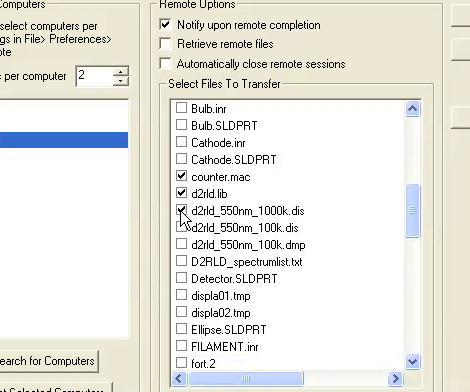
REMOTE Distributed Processing
The enhanced REMOTE functionality in ASAP offers enhanced distributed processing capability, improved file handling to and from machines, access to REMOTE from scripting, and new tools for quickly summing and averaging results.
Exterior Lighting Test Module (ELTM)
SAE, ECE, and FMVSS testing performed with the optional Exterior Lighting Test Module (ELTM) for ASAP.
BIO Toolkit
Features found in the BIO Toolkit add-on for ASAP include extensive eye, skin, and tissue modeling capabilities.
CATIA Module
Use the optional CATIA(r) Module to open native CATIA V5 files from within ASAP and without a separate concurrent CATIA installation. The CATIA Module supports the direct import of CATIA V5 files from release versions r13-23. In addition, all ASAP users may now import STEP geometry files using the same convenient import utility.
Key ASAP NextGen Capabilities
- Automatically create working scripts directly from the Optics Manager
- Quickly create apodized or multi-wavelength sources from the Sources Catalog
- Use pre-defined LED, incandescent, arc, and CCFL sources
- Import measured manufacturer’s source data in distribution file (.dis) format
- Import/Export photometric data in EULUMDAT and IES LM-63-02 formats
- Import lenses from Import lenses from CODE V®, OSLO®, and ZEMAX®
- Gaussian-beam decomposition for wavefront propagation
- Define new media or assign existing media to surfaces from the Media Catalog
- Define new coatings or assign existing coatings from the Coatings Catalog
- Define new scatter models or use existing models from the Scatter Models Catalog
- Model surface (BRDF) and volume scatter
- Define new lenses or use existing lenses from the Lens Catalog
- Create user-defined functions in the Functions Catalog for use in the OM or scripts
- Use digitized coating, spectrum or apodization data from .bmp or .jpg images
- Save digitized coating, spectrum, or apodization data in the User Data Catalog
- Run full radiometric or photometric analyses of complex systems
- Perform numeric and graphical CIE/Chromaticity analyses and Visual Appearance
- Import/Export IGES files using the ASAP CAD Translator
- Import STEP, CATIA, or GTX files using the ASAP CAD Translator
- Use SOLIDWORKS 3D CAD models (license optional) with ASAP
- Write ASAP-specific IGES files from within SOLIDWORKS
- Assign object and layer names in SOLIDWORKS
- Write ASAP-specific IGES files from within Rhinoceros®
- Import geometry and optical properties using the XML file format
- Automatically run parallel processes on available cores on the local machine
- Use multi-core processing for scripts on machines on the Local Area Network (LAN)
- Use all available cores for machines on the LAN for distributed processing
- Use the Workflow Manager (WM) to build complete scripts
- Quickly insert commands with variable input to existing scripts using the WM
- Add command modifiers easily to inserted commands from the WM
- Extensible script editor (ESE) with text markers, auto-indent mode, code folding
- ESE with brace matching, automatic command tips, block code selection
- ESE with horizontal/vertical window splitting for multiview script control
- ESE with colorized syntax, bookmarks, and fully configurable keyboard
- ESE with fully integrated Optimization, Macro, and $SCR Managers
- Optimization Manager (OM) with automatic code parsing to find all defined variables
- Fully integrated OM with Brent’s, Downhill Simplex, and Simulated Annealing methods
- Integrated OM to define variables, objectives, constraints, and exit criteria
- View optimization results with the script editor
- Automatically view, edit and re-insert all defined macros in the Macro Manager
- Create custom forms and auto-generate script in the $SCR Editor
- Easily switch between script languages in the ESE with a simple mouse click
- Integrate scripts in C#, Python, VBScript or JScript languages
- Visualize, analyze, and monitor light distributions using conformal radiometry
- Begin your simulation with one of over 800 example files
- Create your own custom workspace within ASAP NextGen
Workflow Demonstrations
Step 1: System Setup
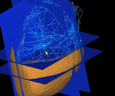
Every optical system simulation begins with an accurate geometrical model. Import your system geometry from a CAD program in formats such as IGES, STEP, or XML, or use the proprietary BRO GTX file format to import from SolidWorks® 3D CAD software, which customers have the option to bundle with ASAP. During import, ASAP users may remove duplicate and unnecessary surfaces, as well as condition geometry for ray tracing. CATIA® users also have the option to open native CATIA files in ASAP. The powerful ASAP script language and spreadsheet-style Builder environments also provide many options for modeling system geometry ranging from simple fixed-dimension surfaces to complex systems with dimensional parameterization, which allows geometrical entities to be treated as variables in system-optimization procedures.
Following geometrical system characterization, optical properties are defined to tell the analysis engine how to treat optical interactions such as transmission, absorption, diffraction, polarization, and scattering. ASAP handles them all. Comprehensive material libraries accelerate system setup but when measurements for new materials must be used, the BRO Digitizer provides maximum flexibility for entering optical properties data and the BSDF fit utility allows fitting complex scatter models including the all-important Harvey scatter model. During system definition, 2D and 3D visualization tools ensure that everything is in place before the next step in the ASAP workflow.
Key System Setup Features
Step 2: Define Sources
Every system requires an accurate source model, and ASAP sources are the best in the industry. ASAP comes standard with hundreds of ready-to-use sources that save users hours.
Key Source Definition Features
Step 3: Run Simulation
Once your system geometry, properties, and sources are defined, you're ready to trace rays. With ASAP, you get the fastest non-sequential ray tracing engine available, as well as REMOTE™ for distributed processing — so you won't be waiting long for results.
Key Simulation Features
Step 4: Perform Analysis
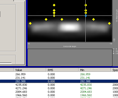
When your ray trace finishes you'll be ready to perform analysis, and the analysis features in ASAP are second to none. ASAP includes everything you need to evaluate your ideas, optimize your system, and visualize, interpret, and share results — taking into consideration the most complex of optical phenomena.
Key Analysis Features
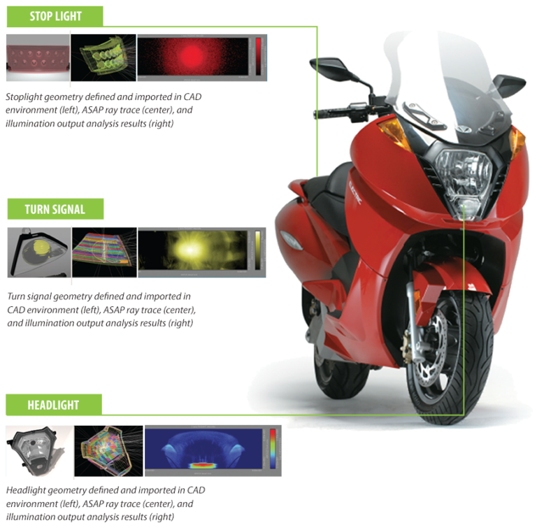
SPOTLIGHT // VECTRIX ELECTRIC SCOOTER: BRO Engineering Services used ASAP to design the headlight, stoplight, and turn signal illumination systems for the Vectrix all-electric scooter. ASAP accurately modeled the slope errors that result from reflector manufacturing processes, as well as scatter from roughness and imperfections in metallic coatings applied to the reflectors. The Vectrix scooter is now in production and available for purchase.
ASAP FAQs
Is ASAP accurate?
ASAP®, the Advanced Systems Analysis Program, will model the finest details of optical systems, which means ASAP users can depend on their simulations to mirror real-world performance. Optical system designers in 35 countries rely on ASAP for virtual prototyping with great accuracy and confidence. ASAP analyses validate designs and support smooth transitions to manufacturing. There is no substitute.
Is ASAP hard to use?
ASAP is a comprehensive set of modeling features capable of modeling more optical phenomena in a single package than any other software application available. These features make up a sophisticated, powerful toolkit for optical-system designers in search of design-validating results. ASAP features have been implemented to be intuitive to learn and apply. With a reasonable time investment, these features are accessible to anyone in need of optical modeling software to support product development.
How can I learn how to use ASAP?
BRO offers a full suite of Optics Training Classes to enable ASAP users to efficiently and accurately solve their optical challenges. Courses include the introductory ASAP tutorial, application-specific ASAP tutorials, and custom training to meet client needs. In addition, a comprehensive set of training and support documents is available in the BRO Knowledge Base.
Do I need to enter my system geometry using the ASAP script language?
ASAP scripting is one of many ways to enter system geometry into the application. Since ASAP is often used in concert with sequential ray-tracing tools, certain configurations of ASAP include integrated translators for popular lens-design applications. CAD users are able to open native CAA V5 CATIA® files from within ASAP, write ASAP-specific GTX files from within SolidWorks®, and import IGES, DXF, and XML files from any CAD application.
Why would I want to enter my system geometry using the ASAP script language?
The ASAP script language creates surfaces that are optimized for ray tracing. This is a key difference between ASAP and other optical software packages powered by solid-modeling engines or coupled directly to CAD programs. These packages often produce geometry elements that are not optimized for ray-tracing engines. Investing the time to model key geometry components within ASAP also makes the full functionality of the ASAP script language accessible, including the ability to automate analyses of multiple design iterations using system parameterization.
How else, besides entering system geometry, can I use the ASAP script language?
ASAP scripting is much more than a way to enter system geometry into the application. It is a tool to ask precise questions about the way light behaves in optical systems.
With minimal keystrokes, ASAP users can analyze light propagation in steps, filter out important subsets of rays being traced through a system model, and interrogate the paths of individual rays or subsets of rays.
ASAP scripting is also a powerful tool to build parameterization, iteration, macro language, and branching into system models. ASAP script users are able to vary key parameters and then optimize systems around these parameters. They can build "IF", "THEN" and "ELSE" statements into models, and even write their own menu-driven programs with user-defined macros.
Can I access the functionality of the ASAP script language with other programming languages?
All ASAP configurations include integrated scripting support for Python, VBScript, JScript, PerlScript, LUAScript, Object Rexx, and DMDScript. The full functionality of the ASAP script language can be accessed from these alternate programming languages. No other optical software application offers such a comprehensive list of scripting options.
What software development resources are applied to ASAP?
ASAP is in continuous development by a team dedicated solely to enhancing ASAP. The ASAP development team continues to work on kernel enhancements, next-generation CAD interoperability, user-interface features, and product styling. ASAP development efforts are supported by a full-time quality control engineer, and a team of technical support engineers — most with Ph.D.s in optical science. All ASAP development efforts follow the "best practices" outlined within the SEI CMMI Capability Maturity Model.
Is ASAP expensive?
We think you will find one of our product configurations to be exactly what you need for your optical design tasks, and its pricing quite reasonable for the value it will add to your product development efforts.